ESP32-关于心率传感器的应用

技术经验 • dingxiao • 阅读数:4480 • 2019年5月20日 14:05

ESP32-关于心率传感器的应用
0x01-心率传感器
心率传感器-PulseSensor,一种常见又廉价的传感器,TB搜索会发现一大堆。
可以应用于简单的心率测试检测设备,手环类似的产品都能看见它的身影。

0x02-Arduino心率库-PulseSensorPlayground
使用Arduino心率库-PulseSensorPlayground进行开发,发现在编译的历程时会出错。例程代码为:
 #include <Arduino.h>
 #include <U8g2lib.h>

 #ifdef U8X8_HAVE_HW_SPI
 #include <SPI.h>
 #endif
 #ifdef U8X8_HAVE_HW_I2C
 #include <Wire.h>
 #endif

 #define ARDUINO_ARCH_ESP32
 #define PinoAnalogico 34

 #define USE_ARDUINO_INTERRUPTS false


 #include <PulseSensorPlayground.h>

 const int OUTPUT_TYPE = SERIAL_PLOTTER;

 const int PIN_INPUT = 34;
 const int THRESHOLD = 550;   // Adjust this number to avoid noise when idle

 PulseSensorPlayground pulseSensor;

 void setup() {

 //    Serial.begin(115200);

 //    pinMode(PinoAnalogico, INPUT);

     pulseSensor.analogInput(PIN_INPUT);
     pulseSensor.setSerial(Serial);
     pulseSensor.setOutputType(OUTPUT_TYPE);
     pulseSensor.setThreshold(THRESHOLD);

     if (!pulseSensor.begin()) {
         Serial.println("PulseSensor.begin: failed");
         for(;;) {
             delay(0);
         }
     }
 }

 const int LCD_WIDTH = 320;
 const int LCD_HEIGHT = 240;
 //const int DOTS_DIV = 30;
 //#define GREY 0x7BEF
 //
 //void DrawGrid() {
 //    for (int x = 0; x <= LCD_WIDTH; x += 2) { // Horizontal Line
 //        for (int y = 0; y <= LCD_HEIGHT; y += DOTS_DIV) {
 //            M5.Lcd.drawPixel(x, y, GREY);
 //        }
 //        if (LCD_HEIGHT == 240) {
 //            M5.Lcd.drawPixel(x, LCD_HEIGHT - 1, GREY);
 //        }
 //    }
 //    for (int x = 0; x <= LCD_WIDTH; x += DOTS_DIV) { // Vertical Line
 //        for (int y = 0; y <= LCD_HEIGHT; y += 2) {
 //            M5.Lcd.drawPixel(x, y, GREY);
 //        }
 //    }
 //}

 #define REDRAW 20 // msec

 short lastMin = 0, lastMax = 4096;
 short minS = 4096, maxS = 0;
 int lastY = 0;
 int x = 0;

 void loop() {
     delay(REDRAW);

     int y = pulseSensor.getLatestSample();
     if (y < minS) minS = y;
     if (maxS < y) maxS = y;
     if (x > 0) {
         y = (int)(LCD_HEIGHT - (float)(y - lastMin) / (lastMax - lastMin) * LCD_HEIGHT);
 //        M5.Lcd.drawLine(x - 1, lastY, x, y, WHITE);

 //    Serial.println(String(y));

         lastY = y;
     }
     if (++x > LCD_WIDTH) {
         x = 0;
 //        M5.Lcd.fillScreen(BLACK);
 //        DrawGrid();
         lastMin = minS - 20;
         lastMax = maxS + 20;
         minS = 4096;
         maxS = 0;
 //        M5.Lcd.setCursor(0, 0);
 //        M5.Lcd.setTextSize(4);
 //        M5.Lcd.printf("BPM: %d", pulseSensor.getBeatsPerMinute());

 Serial.println(String( pulseSensor.getBeatsPerMinute()));
     }
 }
代码编译时出错:

提示:analogWrite没有定义。
查询错误原因,发现很多人都有类似的提示。
https://github.com/WorldFamousElectronics/PulseSensorPlayground/issues/73
这篇issues给出了解决的方法,https://github.com/espressif/arduino-esp32/issues/4。
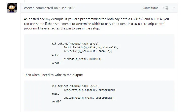
出错的原因是ESP32在是使用arduino进行编译的时候,API中没有analogWrite接口导致的,在ESP32中只提供了ledWrite接口,所以需要通过宏定义加以区分。
遂修改PulseSensorPlayground库源码。
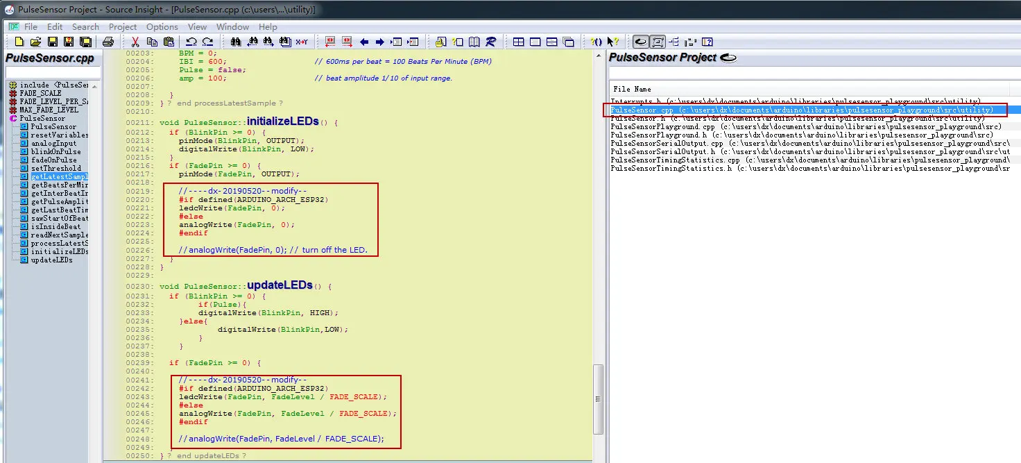
修改完毕后,可以正常编译,但是测试结果是错误的,故放弃此库的使用。
0x03-ESP32_pulsesensor
使用ESP32_pulsesensor方法进行测试,测试结果正常。
上述项目是参考:https://github.com/WorldFamousElectronics/PulseSensor_Amped_Arduino
在此基础上增加OLED显示,代码为:
 /*  Pulse Sensor Amped 1.5    by Joel Murphy and Yury Gitman   http://www.pulsesensor.com
   ----------------------  Notes ----------------------  ----------------------
   This code:
   1) Blinks an LED to User's Live Heartbeat   PIN 13
   2) Fades an LED to User's Live HeartBeat    PIN 5
   3) Determines BPM
   4) Prints All of the Above to Serial
   Read Me:
   https://github.com/WorldFamousElectronics/PulseSensor_Amped_Arduino/blob/master/README.md
   ----------------------       ----------------------  ----------------------
 */
 // May 30,2018
 // ESP32 version by coniferconifer
 // https://github.com/WorldFamousElectronics/PulseSensor_Amped_Arduino/
 // #define ESP32

 #include <Arduino.h>
 #include <U8g2lib.h>

 #ifdef U8X8_HAVE_HW_SPI
 #include <SPI.h>
 #endif
 #ifdef U8X8_HAVE_HW_I2C
 #include <Wire.h>
 #endif


 #define PROCESSING_VISUALIZER 1
 #define SERIAL_PLOTTER  2

 //  Variables
 #define ESP32
 #ifdef ESP32
 #define LEDC_CHANNEL_0     0
 #define LEDC_CHANNEL_1     1
 #define LEDC_TIMER_8_BIT  8
 #define LEDC_BASE_FREQ     5000
 int pulsePin = 34;                 // Pulse Sensor purple wire connected to analog pin 34 , ADC6
 int blinkPin = 13;                 // pin to blink led at each beat
 int fadePin = 5;                  // pin to do fancy classy fading blink at each beat
 #else
 int pulsePin = 0;                 // Pulse Sensor purple wire connected to analog pin 0
 int blinkPin = 13;                // pin to blink led at each beat
 int fadePin = 5;                  // pin to do fancy classy fading blink at each beat
 #endif
 int fadeRate = 0;                 // used to fade LED on with PWM on fadePin

 // Volatile Variables, used in the interrupt service routine!
 volatile int BPM;                   // int that holds raw Analog in 0. updated every 2mS
 volatile int Signal;                // holds the incoming raw data
 volatile int IBI = 600;             // int that holds the time interval between beats! Must be seeded!
 volatile boolean Pulse = false;     // "True" when User's live heartbeat is detected. "False" when not a "live beat".
 volatile boolean QS = false;        // becomes true when Arduoino finds a beat.

 // SET THE SERIAL OUTPUT TYPE TO YOUR NEEDS
 // PROCESSING_VISUALIZER works with Pulse Sensor Processing Visualizer
 //      https://github.com/WorldFamousElectronics/PulseSensor_Amped_Processing_Visualizer
 // SERIAL_PLOTTER outputs sensor data for viewing with the Arduino Serial Plotter
 //      run the Serial Plotter at 115200 baud: Tools/Serial Plotter or Command+L
 static int outputType = SERIAL_PLOTTER;
 //static int outputType = PROCESSING_VISUALIZER;

 U8G2_SSD1306_128X32_UNIVISION_F_SW_I2C u8g2(U8G2_R0, /* clock=*/ 22, /* data=*/ 21, /* reset=*/ U8X8_PIN_NONE);   // Adafruit Feather M0 Basic Proto + FeatherWing OLED

 int tick = 0;

 void setup() {

   Serial.begin(115200);             // we agree to talk fast!

   u8g2.begin();
   u8g2.enableUTF8Print();    // enable UTF8 support for the Arduino print() function
   u8g2.setFont(u8g2_font_unifont_t_chinese2);
   u8g2.setFontDirection(0);

   pinMode(blinkPin, OUTPUT);        // pin that will blink to your heartbeat!
   pinMode(fadePin, OUTPUT);         // pin that will fade to your heartbeat!

   interruptSetup();                 // sets up to read Pulse Sensor signal every 2mS
   // IF YOU ARE POWERING The Pulse Sensor AT VOLTAGE LESS THAN THE BOARD VOLTAGE,
   // UN-COMMENT THE NEXT LINE AND APPLY THAT VOLTAGE TO THE A-REF PIN
   //   analogReference(EXTERNAL);
 #ifdef ESP32
   ledcSetup(LEDC_CHANNEL_0, LEDC_BASE_FREQ, LEDC_TIMER_8_BIT) ; // 8bit precision
   ledcAttachPin(fadePin, LEDC_CHANNEL_0) ; // assaign LED1 to CH0
 #endif
 }


 //  Where the Magic Happens
 void loop() {

   serialOutput() ;

   if (QS == true) {    // A Heartbeat Was Found
     // BPM and IBI have been Determined
     // Quantified Self "QS" true when arduino finds a heartbeat
     fadeRate = 255;         // Makes the LED Fade Effect Happen
     // Set 'fadeRate' Variable to 255 to fade LED with pulse
     serialOutputWhenBeatHappens();   // A Beat Happened, Output that to serial.
     QS = false;                      // reset the Quantified Self flag for next time
   }

   ledFadeToBeat();                      // Makes the LED Fade Effect Happen


     tick = tick + 1;
     if(tick>200)
     {
       tick = 0;
       u8g2.clearBuffer();
       u8g2.setCursor(0, 15);
       u8g2.print("BPM:"+String(BPM));
       u8g2.setCursor(0, 30);
       u8g2.print("IBI:"+String(IBI));
       u8g2.sendBuffer();
     }

   delay(10);                             //  take a break
 }


 void ledFadeToBeat() {
   fadeRate -= 15;                         //  set LED fade value
   fadeRate = constrain(fadeRate, 0, 255); //  keep LED fade value from going into negative numbers!
 #ifdef ESP32
   ledcWrite(LEDC_CHANNEL_0, fadeRate) ;
 #else
   analogWrite(fadePin, fadeRate);         //  fade LED
 #endif

 }
-
暂无评论